Quadcopter Assembly
Please find all components on Area-C shelves.
Basic principles
Feel free to place the components anywhere on the frame but take care of wires. Refer to quadcopters we already have in the lab. Carefully choose zipties, shrinking tubes, double sided tapes or soldering for different situations. Generally, for fixing motor wires we use zipties. Shrinking tubes are for permanent connection between wires when soldering.
Preliminaries
This tutorial assumes you have the following skills:
- ROS Basics or ETHZ Online Course. There are solutions to ETHZ exercises available on Github.
- Soldering, if not, please refer to basic skill video.
- Basic knowledge about LiPo batteries. Answer the following questions. You may read this article.
- What do 3s, 4s mean?
- What does 20c mean?
- What does 1400mAh mean?
- What are the parameters of your battery?
- How to charge LiPo battery? How to measure it voltage using battery meter?
- What’s the minimum voltage to use a LiPo on the quadcopter?
- Basic knowledge about motors. Answer the following questions. You may refer to this article.
- Different types of motors. We are using brushless motor for quadcopters.
- What does KV2200 means? What will be changed if KV number grows?
- What are the parameters of your motors?
Hardware assembly
Introduction
You will need
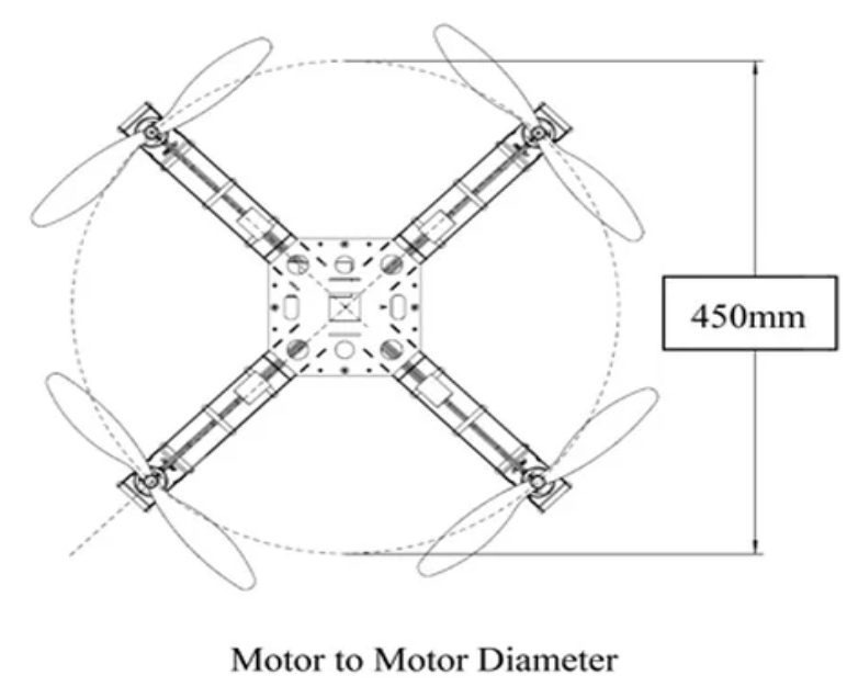
- Quadcopter frame. 250 frame will be a good start. The value 250 means the motor to motor diameter, as shown below.
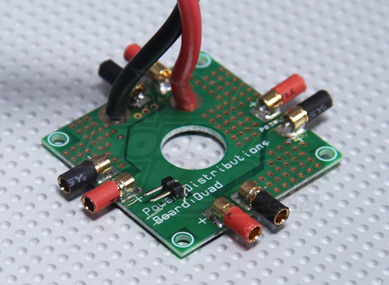
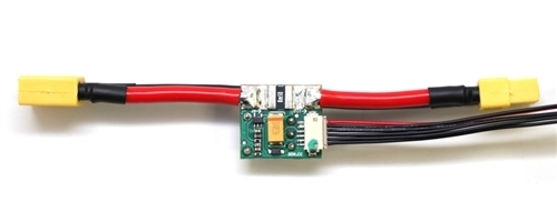
- Power distribution board to distribute power from a battery to 4 ESCs.
- Flight Controller. Use any flight controller available in the lab. Just make sure you have compatible power modules, receivers, GPS, and other additional modules. The documentations for each board are available here.
- Brushless motors and propellers. For mini quad pilots, 3-blade (or tri-blade) propellers are equally popular as the two blades, they are commonly used in both racing and free-style flying. Some people prefer tri-blades because it has more grip in the air. Basically, by adding more blade it’s effectively adding more surface area, and therefore it generates more thrust in the expense of higher current draw and more drag.
Note
There are 2 types of format that manufacturers use.
L x P x B or LLPP x B where L- length, P – pitch, B – number of blades.
For example 6×4.5 (also known as 6045) propellers are 6 inch long and has a pitch of 4.5 inch. Another example, 5x4x3 (sometimes 5040×3) is a 3-blade 5″ propeller that has a pitch of 4 inch. “BN” indicates Bullnose props.
Sometimes you might see R or C after the size numbers, such as 5x3R. R indicates the rotation of the propeller, which stands for “reversed”. It should be mounted on a motor that spins clockwise. C is the opposite, should be used with motors that spins counter-clockwise.
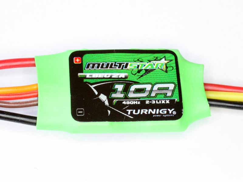
- Electronic speed controller (ESC) controls and regulates the speed of an electric brushless motor. All ESCs comes with a rating. The Turnigy Multistar ESC shown below has a rating of 10A, meaning it can draw a maximum continuous current of 10A. Anything higher than 10A will eventually burn or damage the ESC.
Note
Drawing 10A for a long time (~10mins) will heat up the ESC and damage it as well. Always use a higher rating ESC for your setup. E.g. If your motor draws 10A (at full throttle), use either a 12A or a 15A. If the 12A and the 15A ESC weight approximately the same, choose the 15A. A higher rating ESC will prevent overheating. To handle more power, a high rating ESC will be required. As the rating goes up, the weight, size and cost of the ESC go up as well. Always consider how much power you will need by looking up your motor specification (Max current motor drawn).
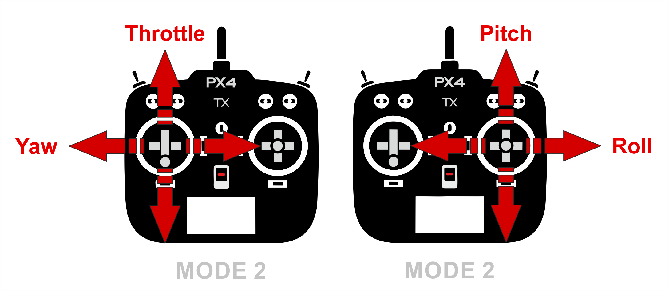
- Remote control system. A remote control (RC) radio system is required if you want to manually control your vehicle. In addition to the transmitter/receiver pairs being compatible, the receiver must also be compatible with PX4 and the flight controller hardware. Spektrum and DSM receivers must connect to a SPKT/DSM input. PPM-Sum and S.BUS receivers must connect directly to the RC ground, power and signal pins (typically labeled RC or RCIN)
The most popular form of remote control unit (transmitter) for UAVs is shown below. It has separate control sticks for controlling roll/pitch and for throttle/yaw as shown
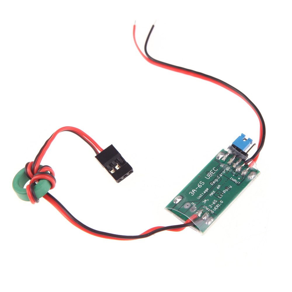
- UBEC (Universal Battery eliminator circuit) to convert voltage to power Odroid (in case you are using it). A BEC is basically a step down voltage regulator. It will take your main battery voltage (e.g. 11.1 Volts) and reduce it down to ~5 Volts to safely power your Odroid and other electronics.
- Power module. It is the best way to provide power for flight controller unit. It has voltage and current sensors that allows autopilot to estimate remaining battery charge precisely. Usually it comes with every autopilot controller as a default kit. Check official documentations to match right power module to a selected flight controller.
- LiPo battery. Assuming you know what is the balancer, cell count and voltage, capacity and C-rating.
Assembly process
- Assemble the frame. Attach the power distribution board to it.
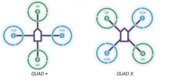
- Mount the motors to the frame. Mind CW and CCW directions. They should be mounted as follows. We usually use X configuration.
Important
Do not install propellers now.
Connect ESCs to motors and plug ESCs to power distribution board. As for now, connect motors to ESCs arbitrary, later you will set them properly by switching any two wires.
Install power module on the frame. One end should be plugged to power distribution board and the other end to the battery. DON’T plug it to the battery for now.
Install flight controller on the frame. Take a look at your flight controller and make sure the arrow is pointing to the front between motor 1 and 3. To mount the controller to the frame, use thick double side tape to damp the vibrations.
Plug cable from power module to
POWERport of your flight controller.Plug buzzer and switch to their corresponding ports on flight controller.
Connect each of your ESCs servo cables to the corresponding MAIN OUT output, eg. motor 1 to MAIN OUT port 1.
Binding process depends on the receiver you use:
FrSky X8R, refer to this document
Spektrum receiver with autobind
- With the transmitter off, power on the receiver.
- The receiver will attempt to connect to the last transmitter it was bound to.
- If no transmitter is found it will enter Bind mode, as indicated by a flashing orange LED. If it doesn’t, press Spektrum Bind button in Radio tab.
- Press and continue holding bind button, turn on your transmitter and allow the remote receiver to autobind.
- When the receiver binds the orange LED turns solid.
Important
Once the receiver is bound to your transmitter, always power your transmitter on first so the receiver will not enter bind mode. If the model enters bind mode unintentionally, shut off power to the model, ensure the transmitter is powered on with the correct model selected, and then power the model on again. The receiver will not lose its previous bind information if it enters bind mode and does not bind.
Spektrum receiver without autobind
- Use AR8000 8ch DSMX Receiver.
- Insert the bind plug in the
BATT/BINDport on the AR8000 receiver and connect RC receiver to AR8000 receiver. - Power the AR8000 receiver by connecting any AUX port to any Pixhawk MAIN OUT port (motor ports). Note that the LED on the receiver should be flashing, indicating that the receiver is in bind mode and ready to be bound to the transmitter.
- Move the sticks and switches on the transmitter to the desired failsafe positions (low throttle and neutral control positions).
- Press and continue holding bind button, turn on your transmitter, the system will connect within a few seconds. Once connected, the LED on the receiver will go solid indicating the system is connected.
- Remove the bind plug from the
BATT/BINDport on the receiver before you power off the transmitter. - Remove the RC receiver from AR8000, and connect it to Pixhawk via port
SPKT/DSM.
Plug the battery and check 4 ESCs has static green LED lighted up. Buzzer will produce sound in the beginning and remain silent. Unplug the battery.
For this stage there’s no need to install Odroid.
Calibration process
- Download
QGroundControlon your computer and open it. - Install PX4 firmware.
- Set the airframe, eg. Generic 250 Frame. Follow steps from this page.
- Calibrate Sensor orientation if any, Compass, Accelerometer, and Level Horizon.
Video for your reference
- Before you can calibrate the radio system the receiver and transmitter must be connected/bound. Follow the steps from this page.
- In
Flight Modestab set:- Modes: Channel 6 (maybe marked as FLAP/GYRO)
- Mode 1: Position. When sticks are released the vehicle will stop (and hold position against wind drift).
- Mode 4: Altitude. Climb and drop are controlled to have a maximum rate.
- Mode 6: Manual.
- Kill switch: Channel 5. Immediately stops all motor outputs. The vehicle will crash, which may in some circumstances be more desirable than allowing it to continue flying.
Hint
If you set everything right, you will see changes in Flight Mode Settings section highlighted as yellow. Also, moving sticks, dials and switches will be reported in Channel Monitor section.
- In
Power tabwrite the parameters of your battery (Number of cells, Full / Empty voltages) and calibrate ESCs if needed. More information on this page and here. - Arm your quadcopter, and check if all motors are rotating in the direction intended. If no, switch any two wires that are connected to ESC. To arm the drone, put the throttle stick in the bottom right corner. This will start the motors on a quadcopter. To disarm, put the throttle stick in the bottom left corner.
- Now you can install propellers. Note that there are CW and CCW propellers as well.
Danger
After you install propellers, make sure to keep battery or receiver disconnected while you are working on your quadcopter. Someone may use transmitter bounded to your drone for their own quadcopter as well. The same transmitter can arm several quadcopters!
- Follow this guide to perform PID tuning for your quadcopter.
Flying
- Read First Flight Guidelines and Flying 101.
- Make sure you switch Kill switch to off. Select Manual as your flight mode.
- Check the battery level, make sure it’s enough to perform your first flight.
- Put the quadcopter in the cage and arm. Slowly add throttle while keeping it in the middle of the cage by controlling pitch and yaw.
Important
Always check the battery before flying
Troubleshooting
- Motors are not rotating while armed and rotates with higher throttle
- Check
PWM_MAXandPWM_MINin parameters and make sure it’s associated with ESCs
- Check
- Motor are not rotating or rotating partially.
- Set
PWM_RATEvalue to default.
- Set